john


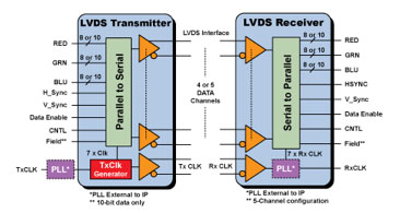
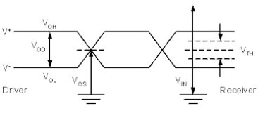
Generally speaking, the LVDS low-voltage differential signal is a standard specification for digital image circuit transmission in modern flat panel displays. From the traditional LCD liquid crystal flat panel display to today's OLED flat panel display, the technical specifications of LVDS are constantly innovating. Specifically, the transmission structure is composed of four differential signal pairs, including three signal differential pairs of red, green, and blue primary colors, and a pair of clock signal transmission pairs. The transmission circuit includes two parts, the transmitting end and the receiving end, and the circuit size layout is determined by the size of the display. Basically, the electrical characteristics of LVDS are very simple. Its transmission speed can reach up to 800Mb/s, and its clock speed can reach up to 100MHz. The voltage level of the differential signal transmitted is between 500Mv and 1V, so the transmission efficiency is extremely high. And has an anti-noise mechanism to ensure the stable quality of the flat-panel display image output.

LVDS low-voltage differential signal transmission architecture
As for how to verify the signal quality of LVDS transmission, the current industry standard is to use an oscilloscope and a high-speed differential probe to measure the signal integrity. The direction of the test can be divided into the measurement of the image signal pair and the clock signal. Right measurement. Because the transmission speed of the LVDS image differential signal pair can reach up to 800Mb/s, according to the fifth harmonic theory of the oscilloscope, an oscilloscope with a 2GHz bandwidth is required to meet the basic test requirements, and its high-speed differential probe must also meet Its corresponding bandwidth requirements. In addition, the test items include the eye diagram test of the image signal, and the rising edge time test of the clock signal. Generally speaking, it is quite simple, because there is no specific test specification for LVDS signals in the industry so far, so each system Design manufacturers have their own test requirements, but the above two test specifications are the most basic, and two parts cannot be ignored at all. As far as the eye diagram test architecture is concerned, we send any set of red, green, and blue signal pairs into the oscilloscope for observation via a differential probe, and turn on the eye diagram test function. As long as the signal evaluation index is the size of the eye diagram, observe the eye diagram height, width, percentage of intersection, rise time, fall time, and Q factor testing, etc. As far as the clock signal is concerned, it is necessary to observe the signal condition of the rising edge of the period. Factors such as the percentage of the pre-shoot signal and the size of the ripple are all important.

LVDS signal eye diagram architecture
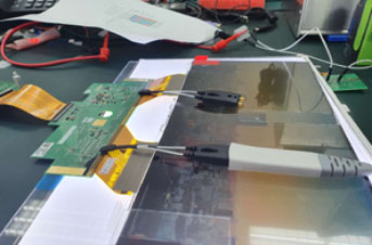
Below, we take the LVDS signal test status of a family car audio display as an example for your reference:
 |
|
RIGOL PVA7250 high-speed differential probe connection structure | RIGOL MSO8204 oscilloscope for eye diagram test architecture |


Contact

contact
RIGOL TECHNOLOGIES, CO. LTD.
Address: No.8, Keling Rd., Hi-tech Development Zone, Suzhou, China
India Local Contact: 1800-572-06-26 (Toll-free)
Taiwan Local Contact: 0800-666-123 (Toll-free)

